Saturday, 24 October 2015

Preparation of Detailed Construction Estimate.

                 Preparation of Detailed Construction Estimate


The preparations of detailed estimate consist of working out quantities of various items of work and then determine the cost of each item. This is prepared in two stages.

Details of Measurement and Calculation of Quantities.

The complete work is divided into various items of work such as earth work concreting, brick work, R.C.C. Plastering etc., The details of measurements are taken from drawings and entered in respective columns of prescribed proforma. The quantities are calculated by multiplying the values that are in numbers column to Depth column as shown below:


Details of measurements form


Details of Measurement Form:


Details of measurements form


Abstract of Estimated Cost:

The cost of each item of work is worked out from the quantities that already computed in the detals measurement form at workable rate. But the total cost is worked out in the prescribed form is known as abstract of estimated form. 4%of estimated Cost is allowed for Petty Supervision, contingencies and unforeseen items.

Abstract of Estimate Form


The Detailed Estimate Should be Accompanied With:


i) Report
ii) Specification
iii) Drawings (plans, elevation, sections)
iv) Design charts and calculations
v) Standard schedule of rates.

Factors to be Considered while Preparing Detailed Estimate:


i) Quantity and transportation of materials: For bigger project, the requirement of materials is more. Such bulk volume of materials will be purchased and transported definitely at cheaper rate.
ii) Location of site: The site of work is selected, such that it should reduce damage or in transit during loading, unloading, stocking of materials.
iii) Local labour charges: The skill, suitability and wages of local laboures are considered while preparing the detailed estimate.

Data for Detailed Estimate:

The process of working out the cost or rate per unit of each item is called as Data. In preparation of Data, the rates of materials and labour are obtained from current standard scheduled of rates and while the quantities of materials and labour required for one unit of item are taken from Standard Data Book (S.D.B).

Fixing of Rate per Unit of an Item.
The rate per unit of an item includes the following:
1) Quantity of materials & cost: The requirement of materials is taken strictly in accordance with standard data book (S.D.B). The cost of these includes first cost, freight, insurance and transportation charges.
ii) Cost of labour: The exact number of labourers required for unit of work and the multiplied by the wages/ day to get of labour for unit item work.
iii) Cost of equipment (T&P): Some works need special type of equipment, tools and plant. In such case, an amount of 1 to 2% of estimated cost is provided.
iv) Overhead charges: To meet expenses of office rent, depreciation of equipment salaries of staff postage, lighting an amount of 4% of estimate cost is allocated.


Saturday, 17 October 2015

Future for Civil Engineering – Trends, Inventions, Inovations.

Some Trends in Civil Engineering Research

  • Structural Engineering
  • Design and Detailing Services
  • Detailing Services
  • Architectural Engineering
  • Computer Aided Design
  • Building Information Modeling
  • Intern Development Program
  • Steam Assisted Gravity Drainage
  • Design of Shell and Spatial Structures
  • Infrastructure Engineering Future, Trends
Structural Engineering
  • Design And Detailing Services
  • Detailing Services
Architectural Engineering
  • Computer Aided Design
  • Building Information Modeling
  • Intern Development Program
  • Steam Assisted Gravity Drainage
  • Design Of Shell And Spatial Structure
Future of Civil Engineering
Design and Detailing Services
Detailing Services
Architectural Engineering, Computer Aided Design
Building Information Modeling
Steam Assisted Gravity Drainage
Design of Shell and Spatial Structures
Architectural Engineering Future, Trends
Infrastructure Engineering Future, Trends

Concrete Retaining Walls


Retaining walls provide lateral support to vertical slopes of soil. They retain soil which would otherwise collapse into a more natural shape. The retained soil is sometimes referred to as backfill.
Retaining walls can be constructed of many different materials and with a variety of building techniques. This discussion will focus on rigid, monolithic, poured concrete walls as the structural material, but steel, timber, and reinforced soil are often used too.

This retaining wall discussion will focus on walls that are constructed from the bottom up and where a stable backslope exists (at least temporarily) prior to wall construction. With poured concrete retaining walls, backfill is placed between the wall and the slope after the wall is constructed.


This discussion will talk about the walls themselves, their design and some important construction considerations. It will not talk about groundwork or compaction, since these are entire topics on their own right. Designers and builders of any kind of retaining wall should be familiar with and follow the procedures and methods for soil preparation and backfill compaction methods dictated by the appropriate local building 
codes.


Retaining Walls
Site
ConcreteNetwork.com
,                                                                                                        


Retaining wall design and wall type selection is driven by several factors.


These factors include:
  • Cost
  • Required wall height
  • Ease and speed of construction
  • Ground water conditions and soil characteristics.
Other factors can include skilled labor and material availability, building codes, site accessibility, aesthetics, local building practice, etc.

 Ultimately, all retaining walls serve to hold back a vertical or near vertical face of soil that would, without adequate retention, cave, slump or slide to a more natural slope.
In most states, retaining wall designs taller than about four feet must be designed by or approved by a qualified, licensed professional engineer. Additionally, it is important to check with and adhere to local building codes prior to any construction, even when walls are shorter than four feet. Retaining walls are, and should always be viewed as load bearing members first, and aesthetic groundscapes second.
Designing any retaining wall requires a knowledge of lateral earth pressure.
Once the lateral earth pressures are known, the wall is checked for stability. This includes checks for wall overturning, base sliding, and soil bearing capacity failures. After the wall is sized, each wall member is checked for adequate strength and steel reinforcing is determined.
One of the most common and telling failures of retaining walls is the inevitable tilting, cracking and bowing of brick, timber and concrete block retaining walls built by homeowners, well meaning builders, and landscapers. These "problems" truly are failures, since the wall has not performed the task it was built to do, and that is to hold back the soil.
The failures also clearly demonstrate the lack of knowledge or design that is required by a successful retaining wall design. By understanding how a wall works, and how it can fail, it is possible to engineer a retaining structure that will meet all foreseen environmental, structural and construction demands.




In most states, retaining wall designs taller than about four feet must be designed by or approved by a qualified, licensed professional engineer. Additionally, it is important to check with and adhere to local building codes prior to any construction, even when walls are shorter than four feet. Retaining walls are, and should always be viewed as load bearing members first, and aesthetic groundscapes second.


One area that can be commonly overlooked, or at least underestimated, is the necessity to drain the backfill of rainwater and/or groundwater. Hydrostatic pressure can cause or induce retaining wall failure, or at least damage.
Drainage of water as a result of rainfall or other wet conditions is very important to the stability of a retaining wall. Without proper drainage, the backfill can become saturated, which has the dual impact of increasing the pressure on the wall and lessening the resistance of the backfill material to sliding. Granular backfill material offers the benefits of good drainage, easy compaction, and increased sliding resistance.

Drainage systems usually utilize weepholes and drainage lines.

Weepholes actually penetrate the retaining wall and drain the area immediately behind the wall. Weepholes should have a minimum diameter so as to permit free drainage. For large walls, 4 inch weepholes are common. Adequate spacing between weepholes allows uniform drainage from behind the wall. Weepholes should always have some kind of filter material between the wall and the backfill to prevent fines migration, weephole clogging, and loss of backfill and caving.
Drainage lines are often perforated and wrapped in geotextile or buried in a granular filter bed, and serve to carry water to the weepholes from areas deeper within the backfill.

HOW TO INSTALL CONCRETE RETAINING WALLS


Prized for their strength and versatility, concrete retaining walls require precise construction methods. With this high level of technicality comes incredible versatility. Poured concrete retaining walls can be colored, textured, accented with embedded objects and much more. When installed properly, concrete offers much more room for customization than any other retaining wall material.

Here are the steps.
  1. Meet with clients and determine what components they want and how the space will function.
  2. Design the walls - determine shape, size and placement.
  3. Remove existing plants, top soil and other debris that may be in the way of construction, Ralston calls this process grubbing.
  4. Lay out and dig the footings.
  5. Build forms.
  6. Add rebar for reinforcement, Ralston places rebar every 16” on center.
  7. Pour footings and wall. If the wall exceeds four feet in height, footings should be poured separately.
  8. Allow concrete to cure.
  9. Create contraction joints every 4-6 feet.
  10. Remove forms and install waterproofing and drainage system.
  11. Finish the surface of the wall as desired.
  12. Install patios, steps and other hardscape elements.
Decorative options for concrete walls:
  • Stamp the surface of the walls - Ralston uses texture skins
  • Do a sponge finish while the concrete is wet - creates a stucco-like look
  • Trowel in a Victorian swirl pattern - looks like old-fashioned plaster
  • Apply an acid stain or color hardener


FOUR COMMON TYPES OF RIGID, MONOLITHIC CONCRETE RETAINING WALLS.


Cantilever Retaining Walls
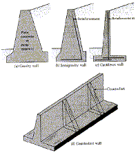
Cantilever retaining walls are constructed of reinforced concrete. They consist of a relatively thin stem and a base slab. The base is also divided into two parts, the heel and toe. The heel is the part of the base under the backfill. The toe is the other part of the base.
  • Use much less concrete than monolithic gravity walls, but require more design and careful construction.
  • Generally economical up to about 25 ft. in height.
  • Can be precast in a factory or formed on site.
Counterfort Retaining Walls
Counterfort retaining walls are similar to cantilever walls except they have thin vertical concrete webs at regular intervals along the backside of the wall. These webs are known ascounterforts.

Counterfort retaining walls:
  • The counterforts tie the slab and base together, and the purpose of them is to reduce the shear forces and bending moments imposed on the wall by the soil. A secondary effect is to increase the weight of the wall from the added concrete.
  • Can be precast or formed on site.
  • Counterfort retaining walls are more economical than cantilever walls for heights above 25 ft.
Gravity Poured Concrete Retaining Walls
  • Gravity retaining walls depend on their own weight and any soil resting on the concrete in resisting lateral earth forces.
  • They are generally economical up to 10 feet in height for cast concrete structures.
  • Usually are sufficiently massive to be unreinforced.
  • Monolithic cast walls are generally formed on site.


GENERAL RETAINING WALL DESIGN

Retaining wall design and wall type selection is driven by several factors.

These factors include:
  • Cost
  • Required wall height
  • Ease and speed of construction
  • Ground water conditions and soil characteristics.
Other factors can include skilled labor and material availability, building codes, site accessibility, aesthetics, local building practice, etc. Ultimately, all retaining walls serve to hold back a vertical or near vertical face of soil that would, without adequate retention, cave, slump or slide to a more natural slope.
In most states, retaining wall designs taller than about four feet must be designed by or approved by a qualified, licensed professional engineer. Additionally, it is important to check with and adhere to local building codes prior to any construction, even when walls are shorter than four feet. Retaining walls are, and should always be viewed as load bearing members first, and aesthetic groundscapes second.
Designing any retaining wall requires a knowledge of lateral earth pressure.
Once the lateral earth pressures are known, the wall is checked for stability. This includes checks for wall overturning, base sliding, and soil bearing capacity failures. After the wall is sized, each wall member is checked for adequate strength and steel reinforcing is determined.
One of the most common and telling failures of retaining walls is the inevitable tilting, cracking and bowing of brick, timber and concrete block retaining walls built by homeowners, well meaning builders, and landscapers. These "problems" truly are failures, since the wall has not performed the task it was built to do, and that is to hold back the soil.
The failures also clearly demonstrate the lack of knowledge or design that is required by a successful retaining wall design. By understanding how a wall works, and how it can fail, it is possible to engineer a retaining structure that will meet all foreseen environmental, structural and construction demands.


Unit Of Measurement

Units of measurement used in past and present surveys are
For construction work: feet, inches, fractions of inches (m, mm)
For most surveys: feet, tenths, hundredths, thousandths (m, mm)
For National Geodetic Survey (NGS) control surveys: meters, 0.1, 0.01, 0.001 m
The most-used equivalents are
1 meter=39.37 in =3.2808 ft
1 rod =1 pole=1 perch=16.5ft(5.029 m)
1 engineer’s chain =100 ft =100 links (30.48 m)
1 Gunter’s chain= 66 ft (20.11 m) =100
Gunter’s links(lk)=4 rods=0.020 km
1 acre=100,000 sq (Gunter’s) links=43,560ft2= 160 rods2=10 sq (Gunter’s) chains=4046.87m2=0.4047 ha
1 rood=1011.5 m2=40 rods2
1 ha= 10,000 m2=107,639.10 ft2=2.471 acres
1 arpent=about 0.85 acre, or length of side of 1 square arpent (varies) (about 3439.1 m2)
1 statute mi=5280 ft=1609.35 m
1 mi2=640 acres (258.94 ha)
1 nautical mi (U.S.)= 6080.27 ft= 1853.248 m
1 fathom=6 ft (1.829 m)
1 cubit=18 in (0.457 m)
1 degree=0.01745 rad=60 min =3600 s
sin 1 =0.01745241
1 rad = 57.30 degree


Estimation of Cement, Sand, and Gravel in Construction

Estimation of Cement, Sand, and Gravel in Construction


In the estimation of cement, sand, and gravel volumes for concrete proportioning, we use the Fuller's Formula. This is an easy way to get a rough estimate in case you are in the field.


Let:

C = number of bags of cement per cubic meter of concrete work  (bag/m3)
S = volume of sand per cubic meter of concrete work  (m3 of sand /m3)
G = volume of gravel per cubic meter of concrete work  (m3 of gravel /m3
c,s,g = cement-sand-gravel ratio (relative amounts of solids by volume in a mixture)

C = 55 / (c+s+g)
S = 0.028*C*s
G = 0.028*C*g

The classes of concrete mixture depends on the cement-sand-gravel ratio (c:s:g).

Class A (1:2:4) = for beams, slabs, columns, all members subjected to bending
Class B (1:2.5:5) = member not reinforced for bending stress
Class C (1:3:6) = for footing (not under water)

Note: We use here 94 lbs Portland Cement per cubic meter of concrete

Example 1:

Determine the number of bags of cement, sand, and gravel of a proposed concrete pavement whose width and length are 100 m x 200 m. The thickness is 100 cm.

Given: Width = 100 m         Length = 200 m               Thickness = 0.1 m

Reqd: number of bags of cement, sand, and gravel

Solution:

Volume of concrete = 100 * 200 * 0.1 = 2000 m3
Pavement = Class A (1:2:4)

C = 55 / (c+s+g) = [ 55 / (1+2+4) ] * 2000 = 15,680 bags
S = 0.028*C*s = {0.028*  [ 55 / (1+2+4) ] * 2 } * 2000 =  800 m3 of sand
G = 0.028*C*g = {0.028*  [ 55 / (1+2+4) ] * 4 } * 2000 = 1760 m3 of sand

Calculate Quantities of Material for Concrete

CALCULATE QUANTITIES OF MATERIALS FOR CONCRETE


Quantities of materials for the production of required quantity of concrete of given mix 
proportions can be calculated by absolute volume method. This method is based on the principle that the volume of fully compacted concrete is equal to the absolute volume of all the materials of concrete, i.e. cement, sand, coarse aggregates and water.

The formula for calculation of materials for required volume of concrete is given by:
                             quantities-of-mateirals-for-concrete-formula
Where, Vc = Absolute volume of fully compacted fresh concrete
W =Mass of water
C = Mass of cement
Fa = Mass of fine aggregates
Ca = Mass of coarse aggregates
Sc, Sfa and Sca are the specific gravities of cement, fine aggregates and coarse aggregates respectively.
The air content has been ignored in this calculation.
This method of calculation for quantities of materials for concrete takes into account the mix proportions from design mix or nominal mixes for structural strength and durability requirement.


Now we will learn the material calculation by an example.
Consider concrete with mix proportion of 1:1.5:3 where, 1 is part of cement, 1.5 is part of fine aggregates and 3 is part of coarse aggregates of maximum size of 20mm. The water cement ratio required for mixing of concrete is taken as 0.45.
Assuming bulk densities of materials as follows:
Cement = 1500 kg/m3
Sand = 1700 kg/m3
Coarse aggregates = 1650 kg/m3
Specific gravities of concrete materials are as follows:
Cement = 3.15
Sand = 2.6
Coarse aggregates = 2.6.
The percentage of entrained air assumed is 2%.
The mix proportion of 1:1.5:3 by dry volume of materials can be expressed in terms of masses as:
Cement = 1 x 1500 = 1500
Sand = 1.5 x 1700 = 2550
Coarse aggregate = 3 x 1650 = 4950.
Therefore, the ratio of masses of these materials w.r.t. cement will as follows is 1:1.7:3.3

The water cement ratio = 0.45
Now we will calculate the volume of concrete that can be produced with one bag of cement (i.e. 50 kg cement) for the mass proportions of concrete materials.
Thus, the absolute volume of concrete for 50 kg of cement =
                           Volume of concrete for 1 bag of cement
Thus, for the proportion of mix considered, with on3 bag of cement of 50 kg, 0.1345 m3 of concrete can be produced.
We have considered an entrained air of 2%. Thus the actual volume of concrete for 1 cubic meter of compacted concrete construction will be = 1 -0.02 = 0.98 m3.
Thus, the quantity of cement required for 1 cubic meter of concrete = 0.98/0.1345 = 7.29 bags of cement.
The quantities of materials for 1 m3 of concrete production can be calculated as follows:
The weight of cement required = 7.29 x 50 = 364.5 kg.
Weight of fine aggregate (sand) = 1.5 x 364.5 = 546.75 kg.
Weight of coarse aggregate = 3 x 364.5 = 1093.5 kg.


Estimation Methods of Building Work

ESTIMATION METHODS OF BUILDING WORKS


The estimation of building quantities like earth work, foundation concrete, brickwork in plinth and super structure etc., can be workout by any of following two methods:

  1.  Long wall – short wall method
  2. Centre line method.
  3. Partly centre line and short wall method.

 Long Wall-Short Wall Method:

In this method, the wall along the length of room is considered to be long wall while the wall perpendicular to long wall is said to be short wall. To get the length of long wall or short wall, calculate first the centre line lengths of individual walls. Then the length of long wall, (out to out) may be calculated after adding half breadth at each end to its centre line length. Thus the length of short wall measured into in and may be found by deducting half breadth from its centre line length at each end. The length of long wall usually decreases from earth work to brick work in super structure while the short wall increases. These lengths are multiplied by breadth and depth to get quantities.

Centre line Method:

This method is suitable for walls of similar cross sections. Here the total centre line length is multiplied by breadth and depth of respective item to get the total quantity at a time. When cross walls or partitions or verandah walls join with main wall, the centre line length gets reduced by half of breadth for each junction. Such junction or joints are studied carefully while calculating total centre line length. The estimates prepared by this method are most accurate and quick.

Partly Centre line and Partly cross Wall Cethod:

This method is adopted when external (i.e., around the building) wall is of one thickness and the internal walls having different thicknesses. In such cases, centre line method is applied to external walls and long wall-short wall method is used to internal walls. This method suits for different thicknesses walls and different level of foundations. Because of this reason, all Engineering departments are practicing this method.